Chinese
 English
 français
 Deutsch
 español
 português
 Nederlands
 日本語
日本語 한국의
한국의




- Casa
- >
Categorie
Prodotti caldi
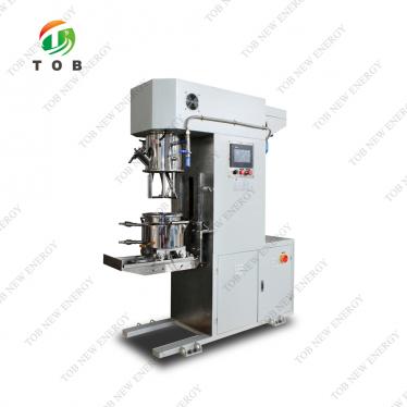
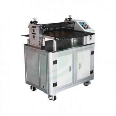
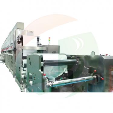
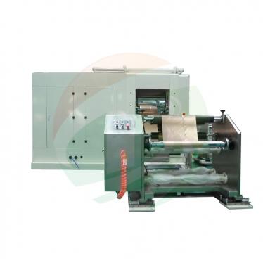
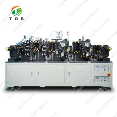
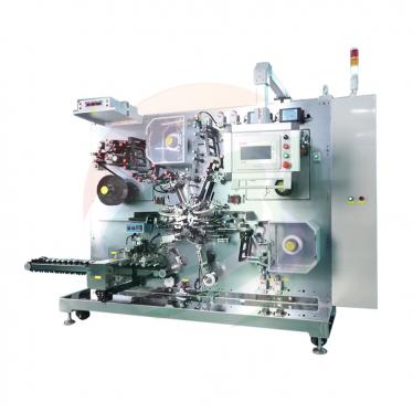
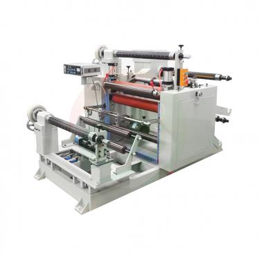
CN215432708U - Lithium Battery Electrode Cutting Machine with Integrated Cleaning Structure
Sep 11,2026A vacuum-fed battery sheet cutting machine whose slices drop straight into an ultrasonic cleaning cavity and leave the machine already clean - cutting and cleaning in one continuous flow.
Full specification and drawings: CN215432708U on Google Patents
Cutting battery sheets into slices is only half the job - the freshly cut pieces then have to be cleaned. The specification of CN215432708U describes what that meant on the production floor before this patent: the cutting machines in use could not clean the cut pieces themselves, so a separate cleaning machine had to stand next to each cutting machine. Machines piled together, the work area stayed dirty, and the footprint grew.
CN215432708U, filed on 26 August 2021 and granted on 7 January 2022, closes that gap inside a single machine. Stacked sheets are picked up one by one by a vacuum carriage, conveyed to a set of tungsten-carbide vertical cutters, and the slices then fall directly into an ultrasonic cleaning cavity built into the same body - clean slices come out of one continuous flow.
Patent Information
| Publication number | CN215432708U |
| Title (original) | 一种带有清洁结构的锂电池的切片机 (Lithium Battery Electrode Cutting Machine with Integrated Cleaning Structure) |
| Inventors | Huang Zhengyao (Dany Huang); Chen Lucai (Tobey Chen) |
| Current assignee | XIAMEN TOB NEW ENERGY TECHNOLOGY Co., Ltd. - the registered entity of TOB NEW ENERGY |
| Filing date | 26 August 2021 |
| Grant date | 7 January 2022 |
| Document type | Utility model (kind code U) |
| Legal status | Active |
| Anticipated expiration | 26 August 2031 |
| Forward citations | Cited by 1 subsequent patent |
| Drawings | 6 figures |
| Official record | Google Patents - CN215432708U |
The Production Problem This Patent Solves
Cutting machines could not clean their own output. Before this patent, cutting machines for lithium battery sheets had no way to clean the cut pieces, so factories had to install separate cleaning machines. The specification lists the consequences directly: machines piled together, a dirty and disorderly work area, and excessive floor space taken up.
The flow had to stay continuous. Sending every batch of cut slices to an external cleaner breaks the material flow and adds handling. The patent's aim, in its own words, is a cutting machine that provides cleaning itself so the cutting operation stays continuous.
How the Mechanism Works
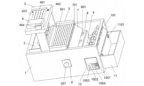
Machine body and sheet supply (claim 1)
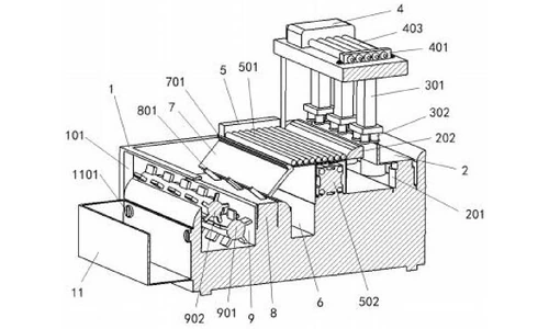
The machine main body is a rectangular box open at the top and on one side, with the top opening reaching only a quarter of the body depth. A lifting seat inside the top opening rises and falls on four lifting columns driven by a push-rod motor, carrying the stack of sheets to be cut. A fixed slide leads from the lifting seat down to the start of the conveyor. Two retractable power plugs stored in notches at the rear power the ultrasonic cavity and the rest of the machine separately; four support legs with anti-skid sleeves stand the body on the floor.
Vacuum sheet transfer (claims 3 and 4)
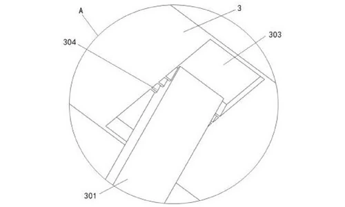
Above the seat stands an n-shaped vacuum carriage, welded to the body, with wiring routed internally. Three moving columns hang from its cross plate; each ends in a detection suction plate fitted with a distance sensor. The columns travel back and forth in their guide grooves under electrically controlled moving rods. As the lifting seat raises the stack, the sensors position the plates over the top sheet, and a vacuum pump - detachably mounted on top of the carriage, with an all-copper core and five vacuum tubes to a fixing plate - holds exactly one sheet to the plates. The carriage then carries that sheet to the conveyor.
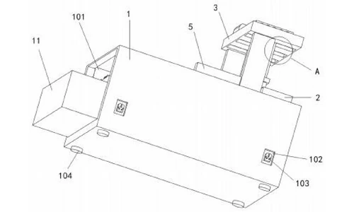
Conveying and feeding to the cutters (claim 5)
Two combined conveyor-roller boxes - the rear one powered by a transmission motor, the front one driven - hold ten conveyor rollers between them that move the sheet forward only. A push plate of bidirectional crawler design sits beyond the rollers, starting with a pusher column fitted with a sensor: once the sheet has fully entered the push plate, the column advances to push the sheet against the cutters and then returns to its start position. A garbage recovery drawer one third of the body depth, with a stainless-steel round handle, sits under the joint between the conveyor boxes and the push plate to catch residues shed during transport.
Tungsten-carbide cutters on an interchangeable plate (claim 6)
At the end of the push plate, a combined cutter plate carries three tungsten-carbide vertical cutters formed integrally with the plate. The cutter plate is detachably connected and interchangeable cutter sets are supplied, so different sheet sizes are cut by swapping the plate rather than rebuilding the machine.
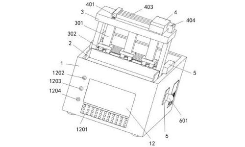
Ultrasonic cleaning, draining and drying (claims 6 and 7)
Cut slices drop straight from the cutter plate into the ultrasonic cleaning cavity. Inside the cavity, a large fluted rolling shaft - its tines aligned with the cutter drop point - tumbles the slices through the cleaning bath, then a small fluted shaft aligned with the draining notch flips them out through the notch into a removable draining box fixed by two large bolts. The draining box has a floor densely pierced with leak holes and lined with water-absorbing cotton, so slices leave the machine rinsed and drained. A dedicated cleaning control panel with an LED progress display and start, pause and keypad controls runs the wash cycle.
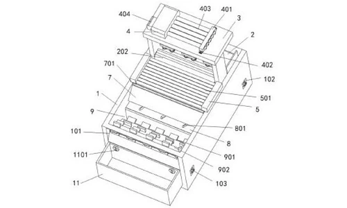
OLED touch control (claim 8)
An OLED touch panel at the geometric centre of the left face shows each sheet's position and the running state of every device. Below it an operation key panel and dedicated keys for the lifting seat, the vacuum pump and the conveyor rollers, together with an intelligent control module in the body, give the operator single-point control of the automatic feeding, cutting and cleaning sequence.
Working cycle
A stack of sheets is placed on the lifting seat. The vacuum carriage moves over the seat, the seat rises, and the vacuum pump holds one sheet to the suction plates. The carriage lays the sheet on the conveyor rollers, which carry it onto the push plate; the pusher column then advances the sheet against the tungsten-carbide cutters. Each slice falls into the ultrasonic cavity, where the fluted shafts tumble it through the wash and pass it out through the draining notch into the draining box - clean, in one continuous flow.
Claimed Benefits
| Benefit | Mechanism responsible |
|---|---|
| Cutting and cleaning in one machine, no separate cleaner required | Ultrasonic cleaning cavity positioned directly under the cutter plate |
| Continuous automatic feeding of stacked sheets | Lifting seat, n-shaped vacuum carriage with three sensor-equipped suction columns, ten-roller conveyor |
| One-sheet-at-a-time transfer without double feed | Distance sensors on the suction plates plus the all-copper-core vacuum pump |
| Quick size change without rebuilding the machine | Interchangeable cutter plate with three integral tungsten-carbide vertical cutters |
| Slices leave the machine rinsed and drained | Fluted rolling shafts feeding the draining notch, draining box with leak holes and water-absorbing cotton |
| Residues contained instead of spreading across the floor | Garbage recovery drawer at the conveyor-to-push-plate joint, round stainless-steel handle |
How It Compares with Separate Cutting and Cleaning Lines
Before this patent, cutting machines for lithium battery sheets had no way to clean their own output, so factories installed separate cleaning machines: machines piled together, a dirty work area and excessive floor space. Here the cut slices drop straight into an ultrasonic cleaning cavity under the cutter plate.
| Dimension | Conventional approach | This patent design |
|---|---|---|
| Workflow | Cutting machine, then a separate cleaning machine | Cutting and ultrasonic cleaning in one continuous flow |
| Workspace | Machines piled together, dirty and disorderly | Single machine with residues contained in a recovery drawer |
| Sheet feeding | Risk of double feed and jams | Vacuum carriage with sensor-equipped suction columns feeding one sheet at a time |
Where This Technology Is Used Today
This patent protects the combined cut-and-clean architecture of TOB's battery sheet cutting machines. The flow it covers - vacuum sheet feed, tungsten-carbide cutting, in-machine ultrasonic cleaning and draining - is how our cutting equipment keeps cut sheets clean without adding floor space.
- Laboratory automatic electrode die cutter machine
- Automatic shear cutter machine for lithium-ion battery electrode cutting
- Sodium-ion battery electrode automatic cutting machine
Related equipment enquiries: request a quote
Frequently Asked Questions
What does patent CN215432708U cover?
It covers a lithium battery sheet cutting machine with an integrated ultrasonic cleaning cavity. A lifting seat and an n-shaped vacuum carriage feed stacked sheets one by one onto conveyor rollers, a push plate advances each sheet against three tungsten-carbide vertical cutters on an interchangeable cutter plate, and the cut slices fall into an ultrasonic cleaning cavity and leave through a draining box - cutting and cleaning in one flow.
Why integrate ultrasonic cleaning into the cutting machine?
Existing sheet cutting machines could not clean the pieces they cut, so a separate cleaning machine had to be added next to each one. The specification lists the consequences: machines piled together, a dirty and disorderly work area, and excessive floor space. Putting the ultrasonic cavity inside the machine keeps the cutting flow continuous and removes the extra cleaner.
How does the machine feed one sheet at a time to the cutters?
Sheets are stacked on a lifting seat that rises towards an n-shaped vacuum carriage. Three moving columns ending in detection suction plates with distance sensors position themselves over the stack, an all-copper-core vacuum pump holds exactly one sheet to the plates, and the carriage places that sheet on ten conveyor rollers that carry it to the push plate and then to the cutters.
What happens to the pieces after they are cut?
Each slice drops directly into the ultrasonic cleaning cavity. A large fluted rolling shaft tumbles the slices through the cleaning bath, and a small fluted shaft flips them out through a draining notch into a draining box whose floor is pierced with leak holes and lined with water-absorbing cotton. A garbage recovery drawer collects residues shed during conveying and cutting.
Is patent CN215432708U still in force?
Yes. It is Active, filed on 26 August 2021, granted on 7 January 2022, with anticipated expiration on 26 August 2031 under the ten-year Chinese utility model term, and it has been cited by 1 subsequent patent.
Full specification and drawings: CN215432708U on Google Patents
Explore the full record: all patents by the TOB technical team
 iscriviti a noi