Chinese
 English
 français
 Deutsch
 español
 português
 Nederlands
 日本語
 한국의




- Casa
- >
Categorie
Prodotti caldi
Patent CN221343111U - Composite Film Forming Device
Nov 03,2026Three supply rollers on a rotating carrier index a fresh roll into the infeed the moment one runs out, so electrode-and-separator composite film forming never stops for reloading.
Full specification and drawings: CN221343111U on Google Patents
Laminated (stacked) lithium-ion batteries are built from composite film in which electrode sheets and separator are thermally bonded - the layers are stacked, heated and pressed between rolls. But the specification of CN221343111U records the production bottleneck in that process: each material web was unwound from a single supply roller, and when the roll ran out the whole line had to be stopped for reloading, holding back production progress.
CN221343111U, filed on 18 December 2023 and granted on 16 July 2024, answers with a turret-style feeding structure. A rotating carrier plate holds three material rollers in the working embodiment; each roller carries its own supply roll. When one roll runs out, a first driving member turns the plate and the next full roll swings into the machine infeed - reel changeover without stopping the forming line.
Patent Information
| Publication number | CN221343111U |
| Title (original) | 一种用于生产锂电池复合膜的成型装置 (Composite Film Forming Device with Turret Unwinder) |
| Inventors | Huang Zhengyao (Dany Huang); Chen Lucai (Tobey Chen) |
| Current assignee | XIAMEN TOB NEW ENERGY TECHNOLOGY Co., Ltd. - the registered entity of TOB NEW ENERGY |
| Filing date | 18 December 2023 |
| Grant date | 16 July 2024 |
| Document type | Utility model (kind code U) |
| Legal status | Active |
| Anticipated expiration | 18 December 2033 |
| Drawings | 4 figures |
| Official record | Google Patents - CN221343111U |
The Production Problem This Patent Solves
Composite film forming needs uninterrupted web supply. In the laminated-battery route, the composite process heats and rolls a stack of electrode sheets and separator into a bonded film. Every metre of that film comes off a supply roller - and the specification notes that production was fed from a single roller, so a depleted roll forced a stop for reloading. Each stop delays the whole line.
Reel changeover should be a motion, not a shutdown. The patent's insight is that the reloading wait can be removed entirely: keep several loaded rollers on one rotating carrier, and when the active roll is exhausted simply index the next one into the infeed position. What used to be a stoppage becomes a rotation.
How the Mechanism Works
Turret feeding structure (claim 1)
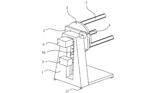
The feeding structure comprises a workbench, a rotating carrier plate and several material rollers. In the working embodiment there are three material rollers, each with one end fixed to the carrier plate and all three distributed evenly around the plate's rotation axis. A first driving member on the workbench turns the plate, so the whole turret indexes. With a supply roll loaded on every roller, exhausting the active roll is by one rotation that brings the adjacent full roll to the machine infeed - cutting changeover time and keeping lithium-ion battery production moving.
Rollers that fit different core diameters (claims 2 to 4)
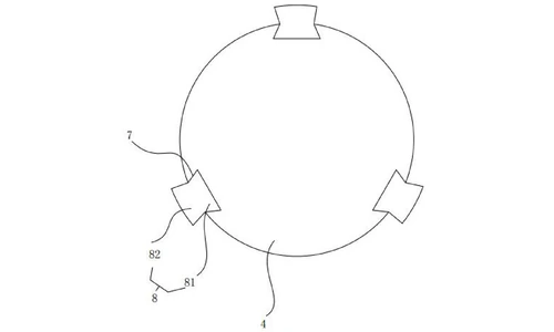
Each material roller carries several clamping grooves machined along its axis. In the embodiment there are three grooves, evenly spaced around the circumference, each with an equilateral-trapezoid cross-section whose longer side faces away from the roller surface. A clamping block is seated in each groove - a fixing part locked in the groove plus an abutment block outside it whose free end is arc-shaped, with the arcs of all three blocks lying on one common circle. Reels with different core inner diameters are therefore centred and held stably on the same spindle, and the trapezoid groove keeps the blocks from slipping out.
Height adjustment of the turret (claims 5 to 7)
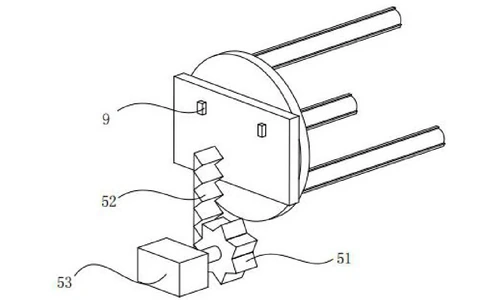
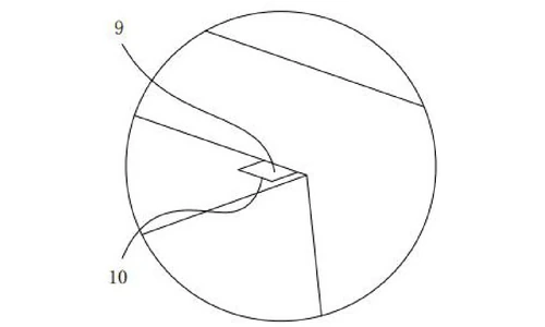
The carrier plate is mounted on the side wall of a sliding plate that travels up and down on the workbench. A second driving member drives that travel: a motor fixed to the workbench turns a gear that meshes with a rack, one end of the rack being welded to the sliding plate and guided in a sliding groove in the workbench. A limit block formed integrally on the sliding plate runs in a limit groove on the workbench, keeping the vertical travel straight and stable. Height control lets the operator put the loaded rollers at exactly the right unwinding level for the downstream forming station.
Mobility (claim 8)
Universal wheels at the four corners of the base let the unit be moved and repositioned on the production floor as line layouts change.
Claimed Benefits
| Benefit | Mechanism responsible |
|---|---|
| Reel changeover without stopping the forming line | Rotating carrier plate indexing the next loaded material roller to the infeed (first driving member) |
| One spindle accepts reels of different core inner diameters | Axial clamping grooves with arc-faced clamping blocks whose arcs lie on one circle |
| Supply rolls run true and stay locked on the roller | Evenly spaced equilateral-trapezoid grooves, blocks held against the roller axis |
| Unwinding height matched to the forming station | Sliding plate raised and lowered by the gear-rack-motor second driving member |
| Stable, repeatable vertical travel | Limit block running in the workbench limit groove |
| Quick repositioning on the production floor | Universal wheels at the four base corners |
How It Compares with Single-Roller Composite Film Feeding
Composite film forming was fed from a single supply roller, so a depleted roll forced a stop for reloading. This device indexes a fresh roll into the infeed the moment one runs out, keeping the forming line moving.
| Dimension | Conventional approach | This patent design |
|---|---|---|
| Supply continuity | One roller; depleted roll stops the line | Rotating carrier plate indexes the next loaded roller to the infeed |
| Core fit | A dedicated spindle per core size | Arc-faced clamping blocks in axial grooves accept reels of different core diameters |
| Unwinding height | Fixed feed height | Gear-rack motor raises or lowers the turret to match the forming station |
Where This Technology Is Used Today
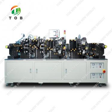
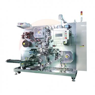
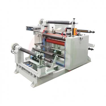
This patent protects the turret feeding architecture of TOB's composite film forming and unwinding equipment. The principle it covers - several loaded rollers on one rotating carrier, indexed into the infeed as each roll runs out - is how our film forming stations keep electrode and separator webs flowing without reload stops.
Related equipment enquiries: request a quote
Frequently Asked Questions
What does patent CN221343111U cover?
It covers the feeding structure of a forming device that produces lithium battery composite film. A rotating carrier plate on a workbench holds several material rollers - three in the working embodiment - distributed evenly around its rotation axis, each loaded with its own supply roll. A first driving member turns the plate so the next full roll reaches the machine infeed when the active roll runs out, and clamping grooves with arc-faced clamping blocks let each roller take reels of different core diameters.
Why use several supply rollers on a rotating carrier instead of one?
Production was previously fed from a single material roller, so when the roll ran out the line had to be stopped for reloading, slowing production. With several loaded rollers on one carrier, exhausting a roll is by rotating the carrier until the adjacent full roll is at the infeed - the changeover becomes a motion instead of a shutdown, which the specification credits with accelerating lithium-ion battery production.
How can one material roller fit reels of different core sizes?
Each material roller has axial clamping grooves - three in the embodiment, evenly spaced around the circumference with an equilateral-trapezoid cross-section. A clamping block sits in each groove, and the arc-shaped free ends of the blocks all lie on one common circle, so reels with different inner diameters are centred and held stably on the same roller.
How is the unwinding height of the rollers adjusted?
The carrier plate is mounted on a sliding plate that travels up and down on the workbench. A second driving member - a motor turning a gear that meshes with a rack welded to the sliding plate - raises and lowers the whole roller set, and a limit block running in a workbench groove keeps the travel straight, so the operator can set the rollers at the height the forming station needs.
Is patent CN221343111U still in force?
Yes. It is Active, filed on 18 December 2023, granted on 16 July 2024, with anticipated expiration on 18 December 2033 under the ten-year Chinese utility model term.
Full specification and drawings: CN221343111U on Google Patents
Explore the full record: all patents by the TOB technical team
 iscriviti a noi