Chinese
 English
 français
 Deutsch
 español
 português
 Nederlands
 日本語
 한국의




- Casa
- >
Categorie
Prodotti caldi
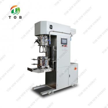
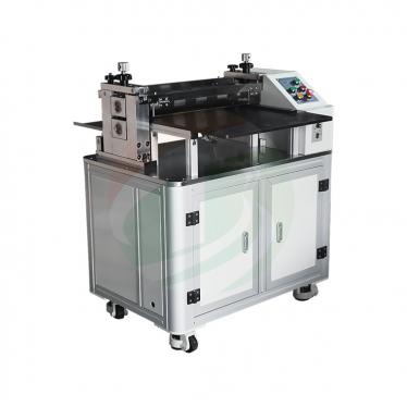
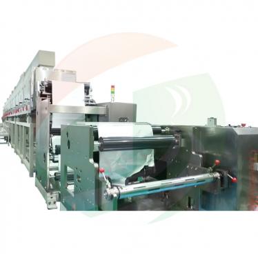
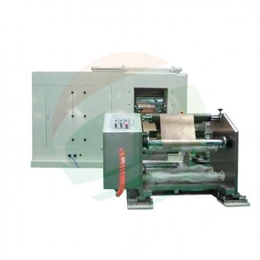
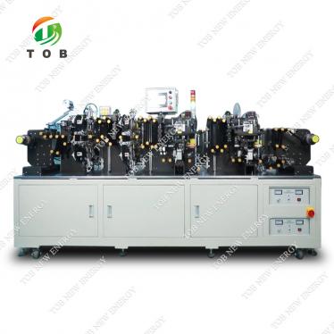
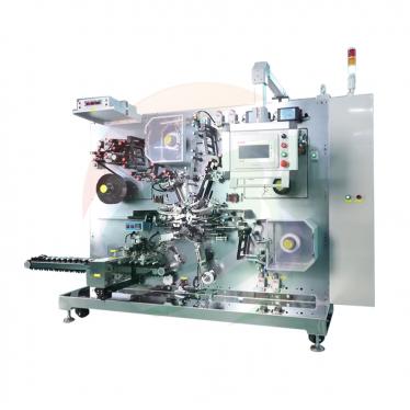
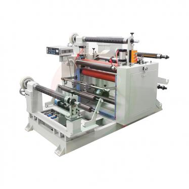
Patent CN215696773U - Three-Roll Electrode Calender
Oct 28,2026Three press rolls arranged as a triangle, continuous brush-and-filter roll cleaning, and a glue-start take-up synchronized with the calender - the structurally stable electrode rolling patent behind TOB roller presses.
Full specification and drawings: CN215696773U on Google Patents
Roll pressing is an indispensable step in manufacturing lithium battery electrode sheets. But the specification of CN215696773U states the problem bluntly: the roller presses then in use for electrode sheets are often structurally unstable, and during rolling an unstable press can damage the electrode sheet and waste raw material. Instead of adding more bracing to a single-nip machine, this patent changes the geometry of the roll set itself.
CN215696773U, filed on 2 September 2021 and granted on 1 February 2022, arranges three press rolls in a triangle - two lower rolls on the workbench and a third roll carried in a liftable calender cover above them. Around that triangle it adds roll-surface cleaning, a synchronized take-up and matched height limiting at both ends of the pass, so the electrode is rolled flat, clean and under steady tension.
Patent Information
| Publication number | CN215696773U |
| Title (original) | 一种结构稳定的锂电池极片辊压机 (Triangular Three-Roll Electrode Calender) |
| Inventors | Huang Zhengyao (Dany Huang); Chen Lucai (Tobey Chen) |
| Current assignee | XIAMEN TOB NEW ENERGY TECHNOLOGY Co., Ltd. - the registered entity of TOB NEW ENERGY |
| Filing date | 2 September 2021 |
| Grant date | 1 February 2022 |
| Document type | Utility model (kind code U) |
| Legal status | Active |
| Anticipated expiration | 1 September 2031 |
| Drawings | 6 figures |
| Official record | Google Patents - CN215696773U |
The Production Problem This Patent Solves
Unstable structures damage the electrode. In the electrode sheet manufacturing process, calendering (roll pressing) is essential. With the presses previously in use, an unstable machine structure lets the electrode sheet shift or distort during rolling, damaging the sheet and wasting raw material.
A single nip leaves no margin for error. A conventional two-roll press squeezes the electrode in one nip between one upper and one lower roll. The patent instead holds the electrode between two lower rolls with a third roll pressing from above, spreading the load over a triangular geometry that stays stable through the whole pass.
Contamination and tension are also rolling defects. Debris stuck to the roll faces can be pressed into the electrode, and uneven tension between rolling and winding can stretch or tear the finished web. The patent treats both as part of the same machine design problem, not as separate accessories.
How the Mechanism Works
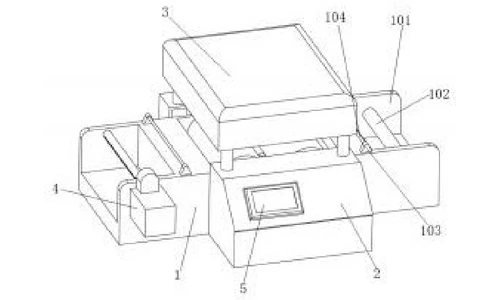
Triangular three-roll geometry (claims 1 and 4)
The workbench carries a rolling groove in its middle. Inside it, a first press roll on a first roll shaft and a second press roll on a second roll shaft form the lower pair. The calender cover above the workbench contains a cover cavity that carries the third roll shaft and the third press roll. The third press roll cooperates with the two lower press rolls to form a triangular rolling structure - the electrode web is guided over the two lower rolls while the closing top roll presses down from above. The specification states that this triangular arrangement makes the rolling process more stable and increases rolling uniformity.
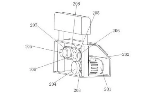
Synchronized roll drive (claim 2)
Inside the rolling motor box at the front of the workbench, the rolling motor drives a first gear, which meshes with a second gear and then a third gear keyed to the first roll shaft. A rolling drive belt couples the third gear to a fourth gear keyed to the second roll shaft. With this chain of gear meshing plus belt transmission, both lower press rolls keep exactly the same rotational speed, which the specification credits with improving the rolling effect.
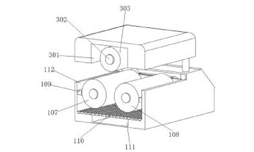
Continuous roll-surface cleaning (claims 3 and 5)
Two rolling brushes are fixed to the inner wall of the rolling groove and cooperate with the first and second press rolls, wiping residue off the roll faces as they turn. Below the groove, a perforated filter plate lets loosened debris drop into an impurity collecting trough underneath. A protection box on the far side of the motor box carries an impurity collection port that opens through the trough, so the cleaned-off residue is collected and drained away rather than re-entering the nip.
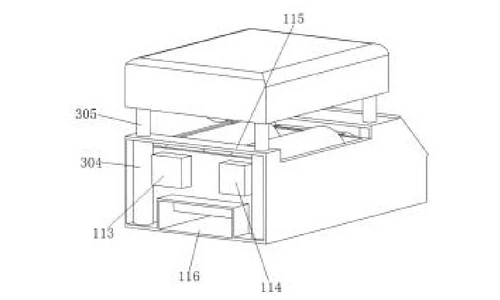
Liftable calender cover with electric cylinders (claim 6)
Four telescopic shafts under the calender cover are driven by electric cylinders housed in the protection box and the rolling motor box and wired to the controller. The cylinders raise and lower the whole cover - including the third press roll - so loading the electrode web between the rolls is quick and convenient. Shaft seals on both lower roll shafts protect the journals.
Synchronized glue-start take-up (claims 7 and 8)
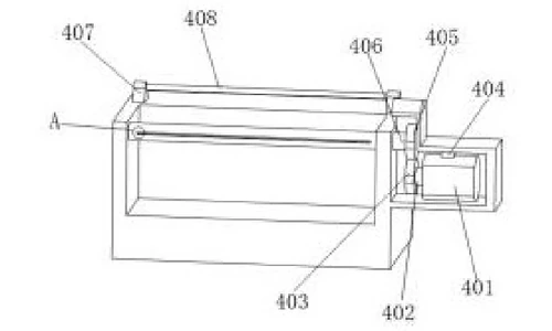
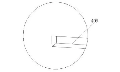
At the left end of the workbench a take-up motor box drives a take-up shaft through a fifth and sixth gear pair. The take-up motor is wired to the same controller as the calender motor, so take-up speed tracks rolling speed and the rolled electrode is not pulled or stretched. A clamping groove on the take-up shaft is coated with adhesive, so the web start is anchored firmly for tight, even winding.
Height limiting at feed and take-up (claims 1, 7 and 8)
A feed trough at the right end of the workbench holds a feed shaft and a feed height-limiting rod; a matching take-up height-limiting rod sits at the take-up side, at exactly the same height. Both rods are made of polished, electroplated steel. The electrode is threaded over the feed rod, through the rolls and over the take-up rod, so it stays horizontal before and after rolling - a further contribution to rolling stability.
Claimed Benefits
| Benefit | Mechanism responsible |
|---|---|
| Stable rolling with improved uniformity across the web | Triangular three-roll arrangement (third press roll in the calender cover over two lower rolls) |
| Equal surface speed on both lower rolls | Gear train plus belt drive from the rolling motor |
| Roll faces kept free of residue during production | Rolling brushes, perforated filter plate and impurity collecting trough draining into the protection box |
| Fast, safe web loading between rolls | Electric cylinders lifting the calender cover on four telescopic shafts |
| No stretch damage while winding the rolled electrode | Take-up motor synchronized with the calender motor, glue-coated clamping groove on the take-up shaft |
| Horizontal web travel before and after the nip | Matched polished steel height-limiting rods on feed and take-up sides |
How It Compares with Two-Roll Electrode Calenders
The specification warns that with the presses previously in use an unstable machine structure lets the electrode sheet shift or distort during rolling, damaging the sheet and wasting raw material. The answer here is geometric: three press rolls arranged as a triangle.
| Dimension | Conventional approach | This patent design |
|---|---|---|
| Structure | Two-roll press, prone to shifting under load | Triangular three-roll arrangement with the third roll in the calender cover |
| Roll cleaning | Residue builds up during production | Rolling brushes, a perforated filter plate and an impurity trough clean continuously |
| Take-up | Winding stretch damages the rolled electrode | Take-up motor synchronized with the calender motor and a glue-start clamping groove |
Where This Technology Is Used Today
This patent covers the mechanical architecture of the triangular-roll electrode calenders in TOB's production line. The geometry it protects - two lower rolls plus a closing top roll in a triangle, with cleaning brushes and a synchronized take-up - is how our calendering equipment keeps electrode rolling stable, clean and even.
Related equipment enquiries: request a quote
Frequently Asked Questions
What does patent CN215696773U cover?
It covers a lithium battery electrode roller press (calender) built around a triangular three-roll arrangement: a third press roll inside a liftable calender cover works with two lower press rolls on the workbench, together with a gear-and-belt drive, brush-and-filter roll cleaning and a glue-start take-up synchronized with the calender speed.
Why arrange the three press rolls as a triangle?
Two lower rolls and one closing upper roll in a triangle hold the electrode in a stable rolling geometry while the top roll presses it down evenly, instead of relying on a single nip between two rolls. The specification states that the triangular rolling structure makes the rolling process more stable and improves rolling uniformity.
How does the calender keep the press rolls clean during production?
Two cleaning brushes fixed to the wall of the rolling groove wipe the surfaces of the first and second press rolls as they turn. Debris brushed off falls through a perforated filter plate into an impurity collecting trough and is drained away through a protection box, so residue cannot be pressed into the electrode.
How is the rolled electrode wound without being stretched or damaged?
A take-up motor drives the take-up shaft through a gear pair and is wired to the same controller as the calender motor, so take-up speed matches rolling speed. The web start is anchored on a glue-coated clamping groove on the shaft, and matched height-limiting rods on the feed and take-up sides keep the electrode horizontal before and after rolling.
Is patent CN215696773U still in force?
Yes. It is Active, filed on 2 September 2021, granted on 1 February 2022, with anticipated expiration on 1 September 2031 under the ten-year Chinese utility model term.
Full specification and drawings: CN215696773U on Google Patents
Explore the full record: all patents by the TOB technical team
 iscriviti a noi