Chinese
 English
 français
 Deutsch
 español
 português
 Nederlands
 日本語
 한국의




- Casa
- >
Categorie
Prodotti caldi
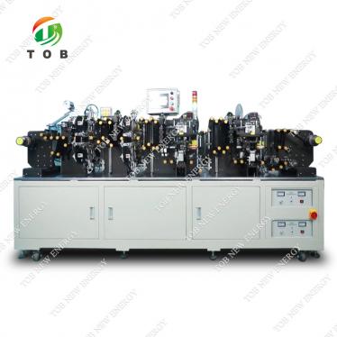
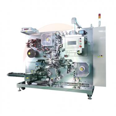
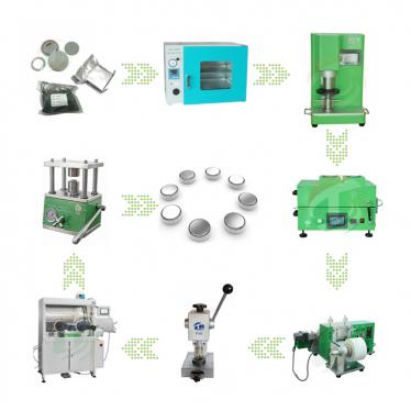
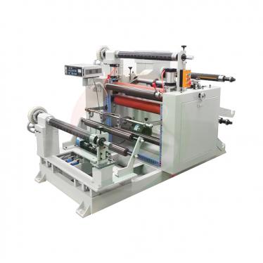
Patent CN215600399U - Electrode Winder with Hot Knife
Oct 22,2026Align, transport, heat-soften, wind and hot-cut a finished electrode strip on one machine - one operator runs the whole step.
Full specification and drawings: CN215600399U on Google Patents
The electrode is the carrier on which a battery charges and discharges - the core of the whole lithium-ion cell. Its manufacture runs from pulping through precision coating, calendering and slitting into strips, on equipment that involves high rolling force, slitting knives, heat and rotating mechanisms. Yet within that chain the winding of the finished electrode strip was an underestimated bottleneck: the specification states plainly that the influence of electrode-side technology such as the winding process is often underrated, and that the process suffered from low efficiency.
CN215600399U, filed on 9 September 2021, turns winding from a manual chore into a single controlled operation. The machine aligns the strip vertical, feeds it through soft-gripped roller sets, heat-softens it for a tight wrap, winds it on a powered platform, and - when the coil is strapped - severs it with a hot cutting blade. One operator, one machine, no separate cutting station.
Patent Information
| Publication number | CN215600399U |
| Title (original) | 一种用于电池生产的电池极片卷绕机 (Electrode Winder with Integrated Hot Knife) |
| Inventors | Huang Zhengyao (Dany Huang); Chen Lucai (Tobey Chen) |
| Current assignee | XIAMEN TOB NEW ENERGY TECHNOLOGY Co., Ltd. - the registered entity of TOB NEW ENERGY |
| Filing date | 9 September 2021 |
| Grant date | 21 January 2022 |
| Document type | Utility model (granted, kind code U) |
| Legal status | Active |
| Anticipated expiration | 9 September 2031 |
| Drawings | 6 figures |
The Production Problem This Patent Solves
The specification explains why electrode winding deserves more attention than it gets. The electrode strip is the physical carrier of charge and discharge, so how it is handled after slitting affects everything downstream. The winding step was inefficient, and the reason is structural: it needed several separate stations - feeding, aligning, winding, and then cutting the finished coil away from the incoming strip - each calling for an operator's hands. CN215600399U consolidates those stations into one machine whose processes are all controlled from one controller.
How the Mechanism Works
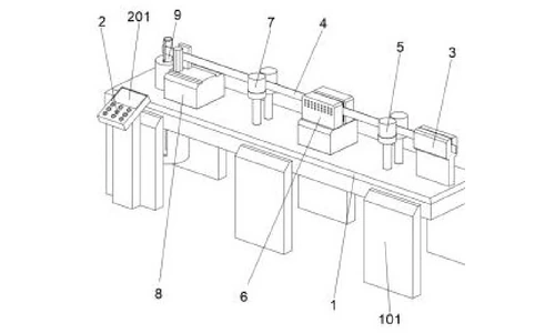
Strip path, from alignment to winding
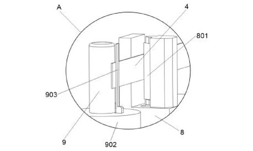
The electrode strip (4) enters the position-aligning seat (3) on the right side of the machine and is drawn out from its left side, so the strip is set in a vertical plane before anything else happens to it. From the seat the strip passes in sequence through the first roller set (5), a heater (6), the second roller set (7), the hot-knife cutter (8) with its hot cutting blade (801), and finally onto the winding rod (9). The machine body (1) stands on a support (101), and the controller (2) with its LED display (201) sits at the front left.
Roller sets that grip without scratching
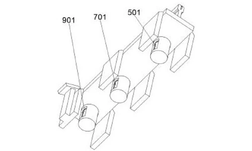
The first and second roller sets (5, 7) move the strip leftward and are each driven directly by their own motor - the first drive motor (501) under the first roller set and the second drive motor (701) under the second. Their outer surfaces are covered with soft rubber, which the specification credits with two jobs: stopping the metal roller surfaces from scratching the electrode, and stopping the strip from slipping down. To make the grip positive, the minimum gap between the roller surfaces is set 1 mm smaller than the electrode thickness, increasing the nip pressure so the strip cannot slide.
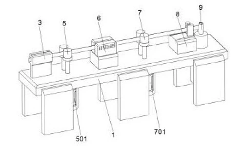
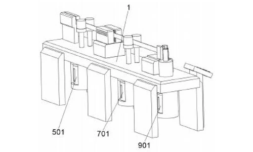
Heating and winding platform
The heater (6) softens the electrode strip before it is wound, so the strip wraps onto the rod without damage. The lower end of the winding rod (9) is joined to a winding platform (902) driven by the third drive motor (901). A movable pressing sheet (903) on the front upper side of the platform presses the strip against the side of the winding rod during winding; its inner side is an arc surface, which enlarges the contact area so the softened strip is pressed firmly as the platform turns the rod.
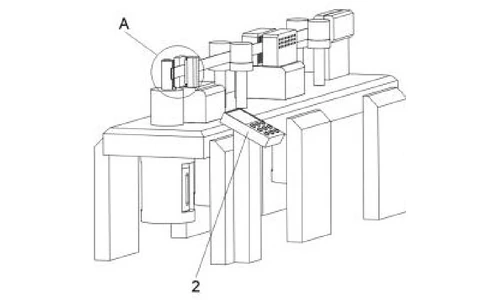
Cut-off and one-operator operation
When the coil is complete and the electrode is secured with a strap, the hot cutting blade (801) on the hot-knife cutter severs the strip, and the operator lifts the finished coil off the rod. Because the heater, the hot-knife cutter and the winding platform are all electrically connected to one controller, the patent achieves what it names as its benefit: one person runs one machine through the whole winding step.
Claimed Benefits
| Benefit | Mechanism responsible |
|---|---|
| One-operator-per-machine production | All stations unified under a single controller |
| Greatly improved winding efficiency | Integrated winding platform and hot-knife cut-off |
| Scratch-free, non-slip strip transport | Soft-rubber-covered roller sets with nip gap 1 mm below strip thickness |
| Accurate winding geometry | Position-aligning seat holding the strip in a vertical plane |
| Tight, damage-free coil build | Heat-softening plus arc-faced movable pressing sheet |
How It Compares with Multi-Station Electrode Winding
The winding step needed several separate stations - feeding, aligning, winding and cutting - which made it inefficient and operator-heavy. This patent unifies the whole strip path in one machine under a single controller.
| Dimension | Conventional approach | This patent design |
|---|---|---|
| Layout | Separate feeding, aligning, winding and cutting stations | All stations unified in one machine under one controller |
| Strip transport | Gripping that can scratch or slip | Soft-rubber-covered roller sets with a nip gap 1 mm below strip thickness |
| Cut-off | Separate cutting step after winding | Integrated hot-knife cut-off on the winding platform |
Where This Technology Is Used Today
This patent covers the winding architecture behind TOB's electrode winders. The arrangement it protects - vertical strip alignment, soft-gripped transport, heat-softening and hot-knife cut-off on one platform - is how our winding equipment finishes electrode coils without a separate cutting operation.
- Electrode making machines - the strip-processing line this winder belongs to
- Electrode preparation equipment - mixing, coating, rolling and slitting ahead of winding
Related equipment enquiries: request a quote
Frequently Asked Questions
What does patent CN215600399U cover?
It covers an electrode winding machine for battery production: a position-aligning seat that holds the strip vertical, two soft-rubber-covered roller sets that transport the strip, a heater that softens it, a hot-knife cutter with a hot cutting blade, and a winding rod on a powered winding platform with a movable pressing sheet - all controlled from one controller.
Why was electrode winding a bottleneck in battery production?
Electrode-side technology such as the winding process was often underestimated, yet the strip is the carrier for battery charge and discharge. The specification states that the winding process suffered from low efficiency, which this machine addresses by combining feeding, alignment, winding and cutting into one controlled operation.
Why are the roller sets covered with soft rubber and set with a smaller gap?
The soft rubber stops the metal roller surfaces from scratching the electrode strip and helps prevent the strip from slipping. The minimum gap between the roller surfaces is set 1 mm smaller than the electrode thickness, which increases the nip pressure so the strip cannot slide during transport.
Why heat the strip before winding it?
The heater softens the electrode strip before it reaches the winding rod, so the softened strip wraps onto the rod cleanly. The movable pressing sheet, whose inner side is an arc surface, then presses the strip firmly against the rod while the platform turns it.
How is the finished coil separated from the incoming strip?
Once winding is complete and the electrode is fixed with a strap, the hot cutting blade on the hot-knife cutter severs the strip. The operator then lifts the finished coil off the winding rod - the cut-off happens in line, with no separate cutting station.
Is patent CN215600399U still in force?
Yes. It is Active, filed on 9 September 2021 and granted on 21 January 2022, with anticipated expiration on 9 September 2031.
Full specification and drawings: CN215600399U on Google Patents
 iscriviti a noi