Chinese
 English
 français
 Deutsch
 español
 português
 Nederlands
 日本語
 한국의




- Casa
- >
Categorie
Prodotti caldi
Patent CN215549102U - Batch Battery Edge-Trimming Device
Oct 19,2026Formed batteries are stacked in a pillar magazine, pushed one cell at a time to a cushioned clamp, and edge-trimmed automatically - a batch answer to the single-cell trimmers that slowed battery lines.
Full specification and drawings: CN215549102U on Google Patents
Polymer lithium-ion batteries are sealed and degassed after formation, and the sealed pouch then needs its edges trimmed. The specification of CN215549102U states the bottleneck plainly: the trimming devices then in use clamped and trimmed one battery at a time, which kept throughput low on the post-formation line.
CN215549102U, filed on 26 August 2021 and granted on 18 January 2022, replaces the one-by-one handling model with a batch magazine. Batteries are stacked between four pillars, a pusher feeds the bottom cell into the working zone, a cushioned clamp holds it, and a motor-driven blade trims the edge - then the next cell is fed. One operator loads the stack; the trimming cycle repeats itself.
Patent Information
| Publication number | CN215549102U |
| Title (original) | 一种电池用切片装置 (Batch Battery Edge-Trimming Device) |
| Inventors | Huang Zhengyao (Dany Huang); Chen Lucai (Tobey Chen) |
| Current assignee | XIAMEN TOB NEW ENERGY TECHNOLOGY Co., Ltd. - the registered entity of TOB NEW ENERGY |
| Filing date | 26 August 2021 |
| Grant date | 18 January 2022 |
| Document type | Utility model (kind code U) |
| Legal status | Active |
| Anticipated expiration | 26 August 2031 |
| Drawings | 4 figures |
| Official record | Google Patents - CN215549102U |
The Production Problem This Patent Solves
Single-cell trimming limits the post-formation line. Lithium-ion polymer cells must be degassed and sealed after formation, and the sealed pouch must then be edge-trimmed. Most of the trimming devices available fixed and trimmed a single cell at a time, and the specification identifies that mode as the cause of low working efficiency in battery cutting (trimming) equipment.
Loading, clamping and cutting had to be unified in one cycle. The patent's answer is a device in which stacked cells are held ready in a magazine, fed forward by a pusher, clamped by a dedicated fixing device, and trimmed by a cutter that moves together with its own stop plate - every step of the trim stroke performed automatically per cell.
How the Mechanism Works
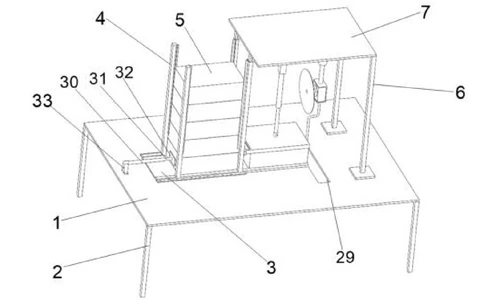
Work plate, legs and mounting frame (claims 1 and 2)
A work plate rests on four legs at its corners. A track plate is fixed on the work plate, with mounting plates formed on both sides that carry mounting holes for secure fastening. Two brackets on the work plate and two of the pillars together support a mounting plate above the work zone; the battery fixing device and the cutting device hang from that mounting plate.
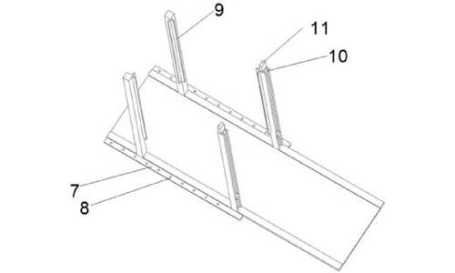
Pillar magazine for the stack (claims 3 and 4)
Four pillars rise from the track plate and enclose a rectangular three-dimensional space in which the batteries to be processed are stacked. Corner holders on the pillars keep the stack from toppling or shedding cells. One face of two opposite pillars carries a guide groove, and the pillar tops carry mounting blocks that locate the battery fixing device.
Battery fixing device (claims 5 and 6)
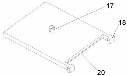
A first mounting rod under the mounting plate carries a first sleeve, in which a first telescopic rod slides. The rod is bolted to a first mounting cylinder on top of a battery fixing plate; two second mounting rods on the plate connect to two sliders that ride in the pillar guide grooves. As the telescopic rod extends, the fixing plate slides straight down onto the cell. The underside of the fixing plate has a groove sized to the width of the battery, lined with a cushion pad, so the clamp both locates the cell laterally and presses it without damage.
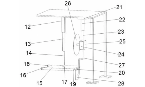
Cutting device and trim-position stop (claims 7 and 8)
The cutting device hangs from the same mounting plate through a second mounting cylinder, a second sleeve and a sliding second telescopic rod that carries a concave mounting piece. Inside the concave piece a motor drives a cutting blade. A folding rod fixed under the concave piece ends in an abutment plate whose left face is aligned with the left face of the cutting blade - the cell is pushed against this plate, which fixes its lengthwise position before the blade trims.
Cutting clearance and pusher device (claims 9 and 10)
The work plate has a hollow groove directly below the cutting device. During the trimming stroke the abutment plate passes down through this groove, letting the blade travel across the full edge of the cell. Feeding is handled by a pusher device mounted on a fixing block on the work plate: a third sleeve slides a third telescopic rod that carries a push plate into the magazine to advance the bottom cell.
Working cycle
Several batteries are stacked inside the space enclosed by the four pillars. The pusher device pushes the bottom cell into the working area until one end of the cell abuts the stop (abutment) plate, then retracts. The battery fixing device slides down and its fixing plate presses the cell. The motor starts, the cutting device descends - the abutment plate moving down through the hollow groove in step - and the blade trims the edge of the cell. The cycle repeats for the next cell in the stack.
Claimed Benefits
| Benefit | Mechanism responsible |
|---|---|
| Cells trimmed in sequence from one loaded stack | Pillar magazine with corner holders plus pusher device feeding the bottom cell each cycle |
| Accurate, repeatable trim position | Abutment plate on the folding rod aligned in the same plane as the cutting blade |
| Damage-free clamping across cell widths | Fixing plate groove sized to the battery width, cushioned underside, sliders running in pillar guide grooves |
| Unobstructed blade travel across the whole edge | Hollow groove in the work plate letting the abutment plate pass below the work surface |
| Compact benchtop layout | Leg-mounted work plate, track plate, shared mounting plate for clamp and cutter |
How It Compares with Single-Cell Trimming
Most trimming devices available at the time fixed and trimmed a single cell at a time, and the specification identifies that mode as the cause of low working efficiency on the post-formation line. This device processes a whole stack instead.
| Dimension | Conventional approach | This patent design |
|---|---|---|
| Throughput | One cell fixed and trimmed per cycle | Pillar magazine holds a stack; a pusher feeds the bottom cell in sequence |
| Trim position | Position set for each cell | Abutment plate aligned in the same plane as the cutting blade gives a repeatable stop |
| Clamping | Rigid clamp, risk of damage | Width-matched groove with cushioned underside and sliders |
Where This Technology Is Used Today
This patent protects the batch feeding and trimming architecture used in TOB's post-formation battery equipment. The cycle it covers - stack, push, clamp, trim - is how our trimming stations process sealed pouch cells without per-cell handling.
- Pouch cell edge-trimming machines - the post-formation trimming stations this architecture protects
- Electrode slitting machines - the upstream slitting step that feeds these cells
Related equipment enquiries: request a quote
Frequently Asked Questions
What does patent CN215549102U cover?
It covers a batch battery edge-trimming device for formed, sealed batteries. Cells are stacked between four pillars on a track plate, a pusher device feeds the bottom cell into the working zone, a battery fixing device with a cushioned width-matched groove clamps it, and a motor-driven cutting blade trims the edge - after which the next cell is fed automatically.
Why feed batteries in a batch instead of one at a time?
The trimming devices in use before this patent fixed and trimmed a single lithium-ion battery per cycle, and the specification identifies that mode as the cause of low working efficiency. Storing the cells in a stack and pushing the bottom cell into the trim position each cycle lets one operator process a whole stack without repositioning each cell by hand.
How does the device hold each battery without damaging it while trimming?
A telescopic-rod mechanism slides the battery fixing plate down along pillar guide grooves until it presses the cell. The underside of the plate has a groove sized to the width of the battery and lined with a cushion pad, so the clamp locates the cell laterally and holds it firmly without damaging the pouch.
How is the trim position kept accurate from cell to cell?
An abutment plate fixed to the cutting device through a folding rod has its left face aligned with the left face of the cutting blade. The pusher advances each cell until its end face meets the abutment plate, fixing the lengthwise position, and the blade then trims at that same aligned position every cycle.
Is patent CN215549102U still in force?
Yes. It is Active, filed on 26 August 2021, granted on 18 January 2022, with anticipated expiration on 26 August 2031 under the ten-year Chinese utility model term.
Full specification and drawings: CN215549102U on Google Patents
Explore the full record: all patents by the TOB technical team
 iscriviti a noi